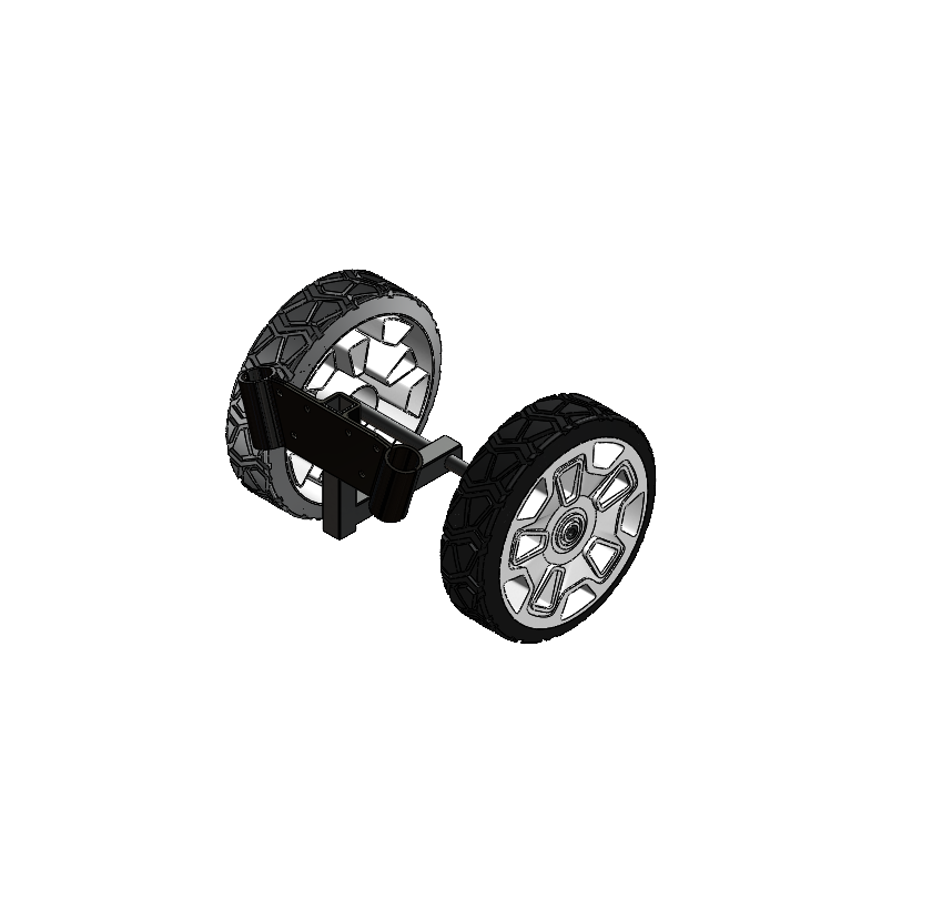
Garden Tiller Solid Modeling
As part of my ME444: Computed Aided Engineering course, I completed a comprehensive project involving the solid modeling, assembly, and visualization of a garden tiller. This project challenged me to leverage advanced CAD techniques, analyze physical properties, and present my work in a technical document, simulating a real-world design and manufacturing environment.
Objective and Approach:
The goal was to create true-to-size 3D models of the garden tiller's primary components, assemble them into subassemblies and a complete assembly, and provide technical documentation and visualizations. This project aimed to reinforce skills in CAD modeling, assembly design, and technical reporting.
Our design process involved:
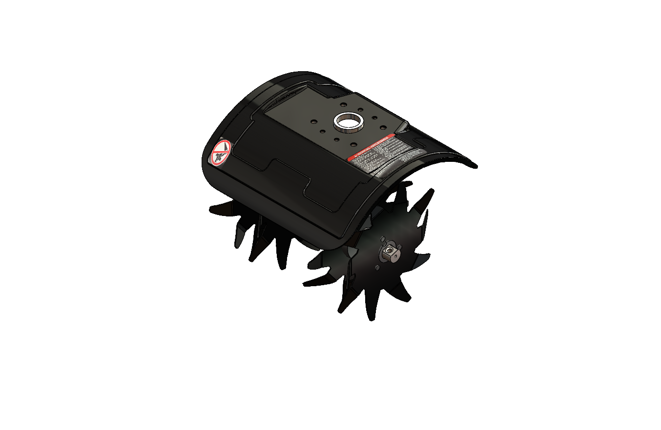
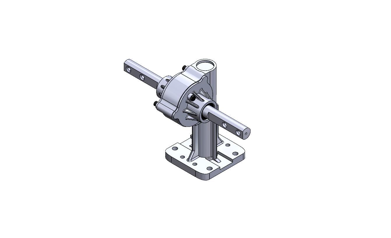
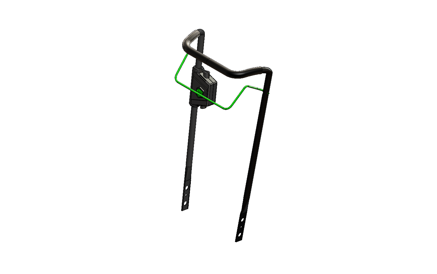
Component Modeling: Using SolidWorks, I modeled components such as the motor, tines, shell, axle, wheels, control module, and handle. Each part was designed with accurate dimensions and realistic materials based on the actual tiller.
Subassemblies and Complete Assembly: I organized individual components into functional subassemblies (e.g., motor assembly) before integrating them into the full assembly.
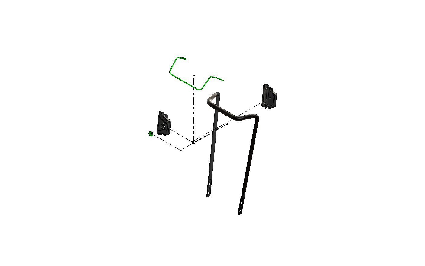
Exploded and Animated Views: Generated exploded views with labeled components and created animations showing the assembly, disassembly, and operational functionality using 3DS Max.


